Why Busway Matters in High-Density Power Distribution
Busway can organize repeated power connections, but a useful comparison with cable starts with the route, load interfaces, operating requirements and complete installed scope.
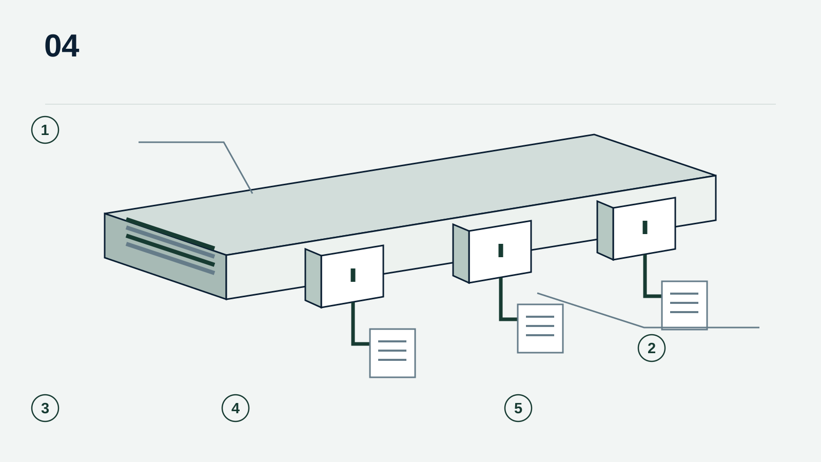
Conceptual busway illustration. The enclosure, conductors, tap-off arrangement, supports and loads are illustrative; the selected system must be reviewed against its manufacturer and project requirements.
- 1Enclosure
- 2Tap-off
- 3Route
- 4Connections
- 5Support + access
Original Aurona editorial illustration
Key takeaways
- Identify feeder, plug-in or track-system requirements before comparing offers.
- Include fittings, interfaces and connection units in the comparison.
- Separate physical expansion provisions from approved electrical capacity.
- Use manufacturer instructions and project review for installation and substitutions.
Start with the distribution problem
A room with repeated equipment connections presents a different purchasing problem from a single point-to-point feeder. The first question is where power must be delivered, how that layout may change and how the operator intends to maintain it. Busway can be relevant to that discussion because it combines conductors, an enclosure and defined connection interfaces into a coordinated distribution system.
That does not make busway the preferred answer for every high-density application. Cable-based distribution may suit a particular route, load pattern or operating model. The useful comparison is between complete, engineered arrangements serving the same requirement. Comparing the price of a straight busway section with the price of conductor alone leaves out much of the work that decides whether either approach is practical.
The word busway covers different systems
Feeder busway, plug-in busway and continuous-access track systems should not be treated as interchangeable descriptions. Eaton’s Pow-R-Way III guide distinguishes system configurations, conductor arrangements and a range of fittings. Starline’s track system uses its own defined plug-in interface. These examples show why the product family and connection method need to be identified before a buyer can compare the apparent flexibility of two offers.
Describe the intended duty in ordinary project terms: a connection between major equipment, distribution along an equipment row, or a run with planned takeoff locations. Then ask the manufacturer to identify the configuration that addresses the approved design. Do not assume that a plug-in unit, joint or end feed from another system will fit or retain the required performance, even if the visible dimensions seem close.
A route is more than its straight-line length
The physical route should show changes in direction, equipment interfaces, penetrations and access constraints. Siemens’ application guide includes layout, measurement and order-entry information because these details affect the system being supplied. The straight run is only part of that package. A revised equipment position can change a transition or fitting without changing the headline electrical rating.
For a useful enquiry, identify the drawing that governs the route and distinguish confirmed dimensions from dimensions awaiting field verification. Assign responsibility for final measurements. Ask whether fittings, hangers, joint components, end closures and interface pieces are included in the offer. If a component depends on a later site measurement, show that dependency in the schedule instead of quietly treating it as ready for release.
References: [2]
Tap-off units connect the system to the load
A tap-off description needs to explain what the connected equipment will receive. Published track-busway information shows that connection units and monitoring can be configured within a manufacturer’s system. The number of tap-offs is therefore only one input. Procurement should also carry the approved connection type, protection requirements, identification and any specified measurement or communications functions.
Create a location schedule with an identifier for each required connection. Keep the initial installation separate from future positions or spare units, and identify who approves later changes. A provision for adding or moving a connection is not proof of unused capacity. The design team must assess loads and protection, and qualified personnel must follow the equipment instructions and applicable safety procedures when performing installation or changes.
References: [5]
Operating conditions remain part of the specification
Enclosure selection and the operating environment deserve the same attention as conductor capacity. A manufacturer’s indoor, outdoor or other application designation relates to a specific tested or documented construction. It is not a general permission to expose every busway section and connection to the same conditions. Make the intended environment visible in the RFQ and ask for any limitations or installation conditions to be stated.
Installation information belongs in the review package as well as in the site handover. Schneider Electric publishes a dedicated Canalis KT installation manual; Siemens likewise points users to product handling and installation instructions. Their existence is a reminder that system selection does not replace correct installation. This article gives no live-work procedure, installation torque, support spacing or acceptance value; those details must come from the applicable project and manufacturer documents.
Compare the complete scope
A fair bid comparison gives each supplier the same route and operating basis. Break the response into the distribution run, connections, supports and interfaces, specified monitoring, documentation and delivery scope. Ask the supplier to separate exclusions from optional enhancements. This makes a lower price easier to interpret and prevents an accessory that appears in one offer from disappearing into an unstated assumption in another.
For a cable alternative, use the same discipline: define its engineered route, termination scope and installation responsibilities rather than estimating equivalence from conductor metal alone. Assess access, planned changes and maintenance through the project’s operating requirements. Avoid a universal claim that one method is always cheaper, safer or quicker. Those conclusions require the actual design, installation circumstances and commercial responses.
Make changes visible before release
Consider a hypothetical equipment row moved after the initial quotation. The number of loads may remain unchanged, while the end-feed position, branch connections and clearances change. A buyer who updates only the quantity schedule can miss those effects. Reissue the affected layout and ask suppliers to identify which parts of their response remain valid. The example is a review method, not an Aurona project claim.
Keep an explicit record of the accepted manufacturer, system designation, drawing revision and approved deviations. If an equivalent is proposed, compare it against the same interfaces and arrange technical review before treating it as interchangeable. Availability, manufacturing release and delivery remain commercial questions to confirm with the supplier; a catalogue option is not a committed lead time.
Flexibility is useful when the boundaries are clear
Busway deserves consideration where its connection arrangement fits the distribution problem. Its value becomes clearer when buyers can explain the route, identify each load interface and understand what future change actually requires. The result should be a coordinated package that an engineer, installer, supplier and facility operator can read without constructing a different set of assumptions.
The best next step is therefore a reviewable specification, not a product slogan. Assemble the current drawings, mark unresolved dimensions, list the required connections and ask for a response that separates included scope, qualifications and alternatives. That approach supports an informed busway-versus-cable decision while leaving system design and approval with the responsible professionals.
Sources & further reading
- Pow-R-Way III busway design guide, DG017002EN
Eaton · Accessed
- Sentron Busway Systems: selection and application guide
Siemens · Accessed
- Starline Track Busway
Starline / Legrand · Accessed
- Canalis KT Busbar Trunking System: Installation Manual, QGH3492101
Schneider Electric · · Accessed
- PowerWave 2 busway
Eaton · Accessed