The Electrical Path Through a Modern Data Center
Following power from the incoming supply to the rack reveals the interfaces that buyers must keep aligned across equipment, conductors, grounding and cooling.
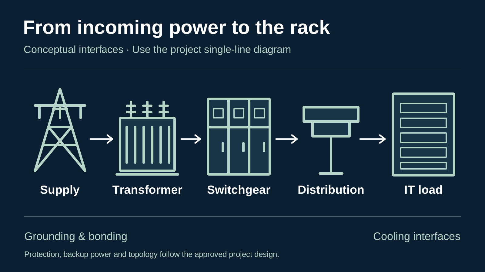
Conceptual electrical relationships, not a single-line diagram. Actual topology, backup power, protection, redundancy and cooling interfaces are project-specific.
Original Aurona editorial illustration
Key takeaways
- Use the project single-line diagram to establish the actual electrical path.
- Track equipment connections, responsibilities and drawing revisions across separate packages.
- Treat topology changes and substitutions as engineering decisions.
- Coordinate grounding and thermal inputs without assuming that purchasing a component approves the system.
Read the system before the equipment list
A data center purchase schedule can separate transformers, switchgear, conductors and cooling into different packages. Electricity does not recognize those purchasing boundaries. An equipment connection approved in one package must still match the item purchased in another. Following the electrical path is therefore a useful way to organize questions before quotations arrive, especially when multiple suppliers work from different drawings or revision dates.
The Department of Energy’s design guide describes a distribution system that can include incoming service, switching equipment, alternate sources, UPS equipment and downstream distribution. That is a family of arrangements, not one mandatory sequence. A facility’s actual single-line diagram determines what connects to what. The illustration accompanying this article deliberately simplifies those relationships and must not be used to design, install or operate a power system.
References: [1]
Incoming power establishes a shared starting point
Begin with the information that is supposed to remain consistent across the procurement package: the agreed service interface, system voltages, frequency, required capacity and the current design revision. Identify who owns each incoming connection. A utility interface drawing, an equipment outline and a civil layout answer different questions; combining them into one unlabelled attachment can conceal a missing approval or an unresolved boundary.
Ask the responsible engineer to identify the governing electrical studies and the conditions under which equipment must operate. Procurement should transmit approved requirements and log gaps, rather than infer fault ratings or protection settings from a product brochure. If the incoming arrangement changes, issue the change to all affected packages. Updating the transformer schedule alone may leave a switchgear interface or conductor connection based on an older assumption.
Transformation and switching are connected decisions
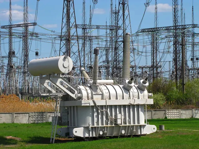
Transformers, switchboards, switchgear and panelboards perform different functions in a distribution system. Manufacturer portfolios list these as distinct equipment families for a reason. A purchase description that treats the names as interchangeable can obscure the intended construction, protection, connection arrangement or documentation. Use the terminology in the project specification and request clarification where a quotation uses a different description.
For a transformer-to-switchgear connection, record which package supplies the transition and what drawings govern it. Terminal position, phase identification, mounting geometry and conductor entry should be visible to both suppliers. A quoted item can match the equipment schedule yet leave the connection unpriced. A short interface register that names the responsible party and the approval drawing is often more useful than repeating the same catalogue description in several places.
References: [3]
Continuity depends on the chosen architecture
Backup generation, UPS equipment and transfer arrangements belong to an operating strategy established by the project team. Schneider Electric’s comparison of UPS configurations illustrates that multiple distribution arrangements are possible. A UPS nameplate or a general redundancy label does not explain the whole system. Buyers need to know which configuration the project has selected and which documents describe its operating and maintenance modes.
From a procurement perspective, identify what the quotation includes around the main equipment: associated switching, monitoring, interfaces, documentation and any specified testing. Ask who will reconcile these boundaries with other suppliers. Do not accept a substituted arrangement merely because its headline capacity appears similar. Any change that affects continuity or maintenance requires the responsible designers and equipment manufacturers to assess the complete arrangement.
References: [2]
Distribution brings the requirement to the rack
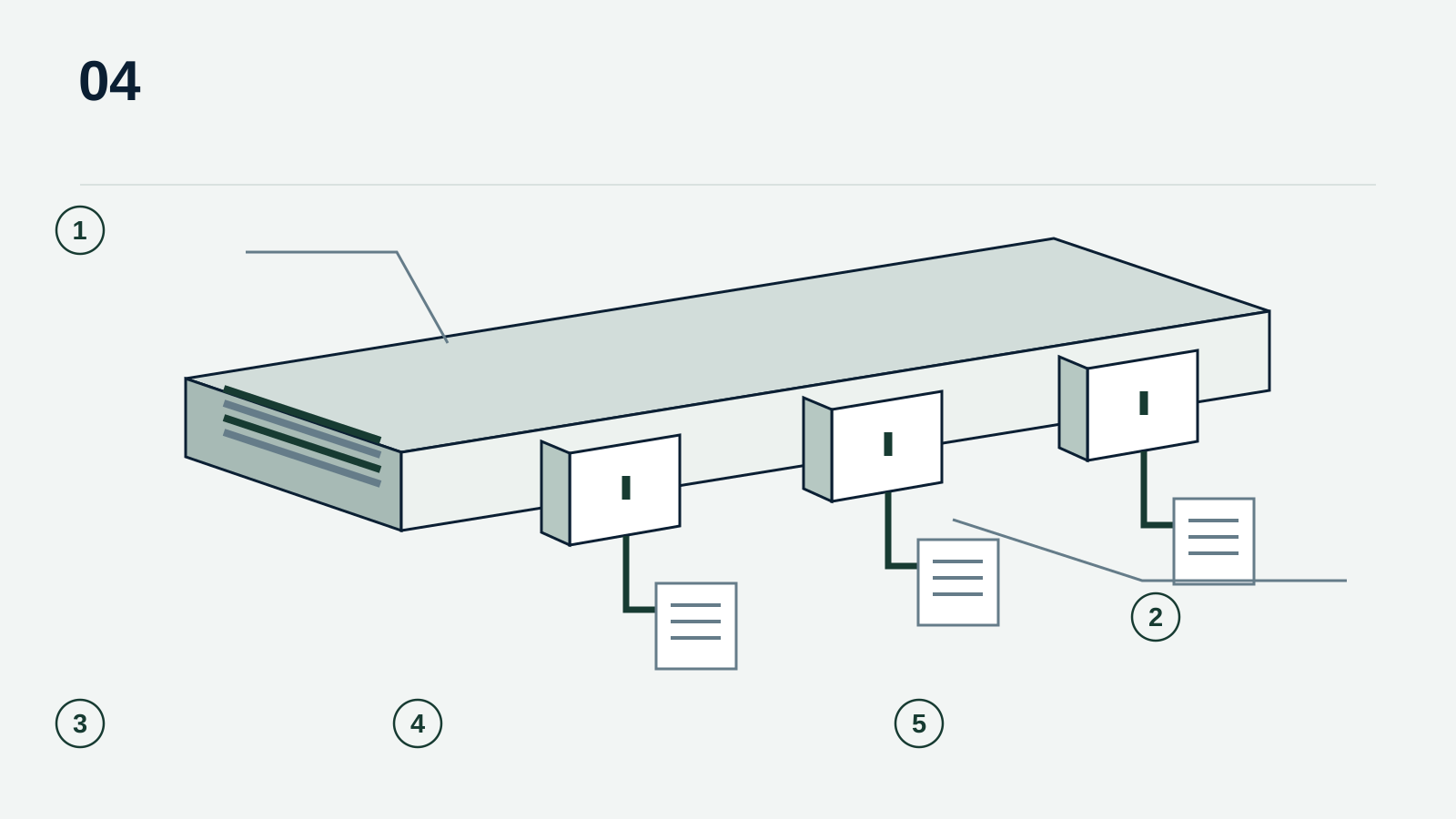
Downstream distribution may use busway, cable-based circuits, distribution panels and rack-level equipment in combinations selected for the facility. Track busway is one example of a system that provides distributed connection points along a run. Eaton’s published PowerWave 2 information describes the relationship between the track, end feed, tap-off boxes and monitoring options. Those options belong to a particular system; they should not be assumed to transfer between brands or generations.
An RFQ for this part of the path should connect the load schedule to a physical route. Record the planned connection locations, outlet or termination requirements, identification convention and any monitoring data the operator needs. Keep future expansion as an explicit design allowance rather than an unqualified promise. Additional physical connection points do not by themselves establish spare electrical capacity or permission to add loads.
References: [4]
Grounding and cooling cross purchasing boundaries
Grounding and bonding need their own documented interfaces. A bar, lug, enclosure connection or jumper should be described by the approved material, geometry, termination and finish requirements. Procurement can check that these inputs are present, but cannot establish a safe grounding arrangement from the appearance of a component. Where a conductor or enclosure changes, flag the related grounding details for engineering review instead of assuming the original detail still applies.
Cooling is another connected system, not a final accessory. Electrical equipment contributes heat, while IT equipment imposes operating conditions that the thermal design must support. DOE’s guide treats electrical and mechanical efficiency together. The purchasing implication is to share the agreed load basis and equipment information between disciplines, while keeping cooling-system design, operating limits and equipment compatibility with the responsible project team.
References: [1]
Avoid treating one architecture as universal
Discussion of new data-center power architectures can make an established diagram look outdated before its project is complete. Schneider Electric’s paper on DC architectures identifies additional questions around converters, UPS bypass, earthing, fault analysis and protection. The procurement lesson is not that one architecture should replace another. It is that a voltage or conversion change is a system decision with implications beyond the item being quoted.
When evaluating an alternative, request a clearly separated proposal with its assumptions and affected interfaces. Keep the specified base offer available for comparison. Record what requires approval and who can provide it. A vendor’s general technical reference can help frame questions, but it is not evidence that the proposed equipment is suitable for the project or available through Aurona.
References: [5]
A useful handoff follows the interfaces
Before releasing a package for quotation, walk through it in the same order as the power path. Check that every equipment boundary has an owner, every drawing has a revision and every open question has a disposition. This does not require an elaborate new software process. A short, controlled schedule shared with the specification and drawings can make unresolved issues visible to everyone responding.
The strongest result is a set of comparable responses that state what is included, what remains conditional and which decisions still need technical approval. That gives buyers a clearer basis for commercial comparison while preserving the distinction between sourcing support and project engineering. A complete equipment list is useful; a list whose interfaces agree is much more useful.
Sources & further reading
- Best Practices Guide for Energy-Efficient Data Center Design, revised July 2024
U.S. Department of Energy / NREL · Accessed
- Comparing UPS System Design Configurations
Schneider Electric · · Accessed
- Power distribution data center infrastructure (grey space) solutions
Eaton · Accessed
- PowerWave 2 busway
Eaton · Accessed
- Necessary Considerations for Designing DC Architectures in Data Centers
Schneider Electric · · Accessed